English
 English
 عربى
Industry News
Home / News / Industry News / Air Dryer Components Explained: Heat Exchangers, Drain Valves and Controls

Content
A pressure dew point that creeps up two or three degrees over eighteen months is rarely a refrigeration fault. In most industrial compressed air dryers, the cabinet, the refrigerant compressor and the controller outlive everything around them. What actually sets the dew point is the condition of the heat exchange surfaces, the separator, the drain valve and the filter elements. When a plant swaps out an entire dryer to cure a moisture complaint, it usually replaces perfectly serviceable hardware and inherits the same clogged strainer, undersized drain line or channelled desiccant bed.
The practical conclusion is simple: treat air dryer components as a system of parts with different wear rates, specify them against measurable numbers, and keep the fast-wearing items on the shelf instead of the whole unit.
Whether you are sourcing spares or writing a specification, a dryer breaks down into six functional groups. Each one can be evaluated on its own, and each one can quietly drag the outlet dew point away from the nameplate value.
The two dominant dryer families look similar on a P&ID but share very little in the spare parts bin. Refrigerated dryers reach roughly +3 °C pressure dew point and rely on a sealed refrigerant circuit. Desiccant dryers push to −40 °C or lower and rely on a regenerating bed plus purge hardware that must be leak-tight to stay economical.
| Component group | Refrigerated dryer | Desiccant dryer | Typical first failure |
|---|---|---|---|
| Heat exchange core | Air-to-air plus air-to-refrigerant exchanger | Air-to-air exchanger only | Fouling and internal leaks after five to eight years |
| Drying medium | None | Activated alumina or silica gel beads, 3-5 mm | Bead crushing or channelling; dew point drifts upward |
| Switching hardware | Expansion valve, hot gas bypass valve | Purge orifices, shuttle and check valves | Purge valve leakage wasting 12-18% of rated flow |
| Separation | Cyclone separator with demister | Inlet separator plus particulate after-filter | Demister collapse at sustained high flow |
| Drainage | Timer or level-sensing trap with strainer | Same, plus purge exhaust handling | Strainer blockage and stuck solenoid coils |
| Controls | Evaporator temperature control | Dew point sensor, timer, heater control | Sensor drift that hides a real dew point rise |
Buying a refrigerated unit when the process needs −40 °C is a specification error, but buying a desiccant unit without checking purge loss is an energy error that shows up monthly on the compressed air bill.
In field investigations, the separator and the drain account for more wet-air complaints than the refrigerant circuit. A demister sized for 100% of rated flow will deform once a plant adds a second shift and runs at 115% for a few weeks. A timer drain set to open for four seconds every ten minutes discharges condensate reliably but also vents compressed air on every cycle; a level-sensing drain solves that, provided the sensor is cleaned on schedule.
Drain lines deserve particular attention. Traps discharging into a common header, lines with an upward lift greater than roughly one metre, or lines reduced to a smaller bore than the trap outlet will hold condensate in the separator bowl and push it downstream in slugs. If the after-filter element shows free water rather than aerosol, check the drainage path before touching the refrigeration charge.
Component specifications are only useful when they are numeric. These are the values worth demanding in writing:
Brazed aluminium plate exchangers dominate mid-range refrigerated dryers because they pack surface area into a small body. Copper tube-and-fin cores cost more but tolerate vibration and thermal cycling better in mobile or skid-mounted installations. Stainless steel wetted parts matter where the condensate is aggressive or where food and pharmaceutical audit standards apply.
Elastomer choice is not a detail. Seals and hoses must be compatible with whatever refrigerant the circuit carries, whether that is R134a, R513A or a newer low-GWP blend, and with the lubricant in circulation. A nitrile seal specified for an older refrigerant can harden within a season and start weeping oil. Filter elements, for their part, should be rated by efficiency class and dirt-holding capacity, not only by micron number, because two elements with the same nominal rating can differ by a factor of three in service life.
A realistic stocking list follows the wear curve rather than the parts catalogue. Pre-filter elements and drain strainers are consumables on a quarterly or differential-pressure basis. Condenser fins need cleaning whenever ambient dust accumulates, which in foundries and cement plants can mean monthly. Desiccant charges are typically replaced every three to five years, sooner if the inlet separator is letting liquid water through. Dew point sensors drift and should be verified annually against a reference instrument, otherwise the controller will report a healthy dryer that is not drying.
Keeping one drain solenoid, one level sensor, one set of filter elements and one pressure gauge per dryer on site removes most of the downtime risk for the price of a few percent of the unit cost.
The instruments and couplings around a dryer cabinet deserve the same scrutiny as the internals. A glycerine-filled pressure gauge rated to the correct range gives maintenance staff a local reading that does not depend on a supervisory system, and a liquid-filled case survives the pulsation that dry piston compressors send downstream. Where the same instrumentation and coupling standards are used across hydraulic and pneumatic circuits, plants reduce the number of unique fittings on the shelf.
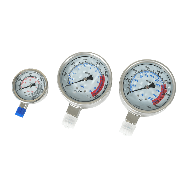 Hydraulic Pressure Gauge with Glycerin-Filled CaseProvides local hydraulic circuit readings with glycerin damping, overload protection, and stainless wetted parts for pump, tool, and manifold monitoring.View Product →
Quick-connect couplings matter most during service. Being able to isolate a filter housing, vent it, and reconnect without tools shortens element changes and cuts the chance of cross-threading a brass fitting under time pressure. Stainless and plated steel options cover both compressed air and hydraulic service, which is useful where maintenance teams share equipment across departments.
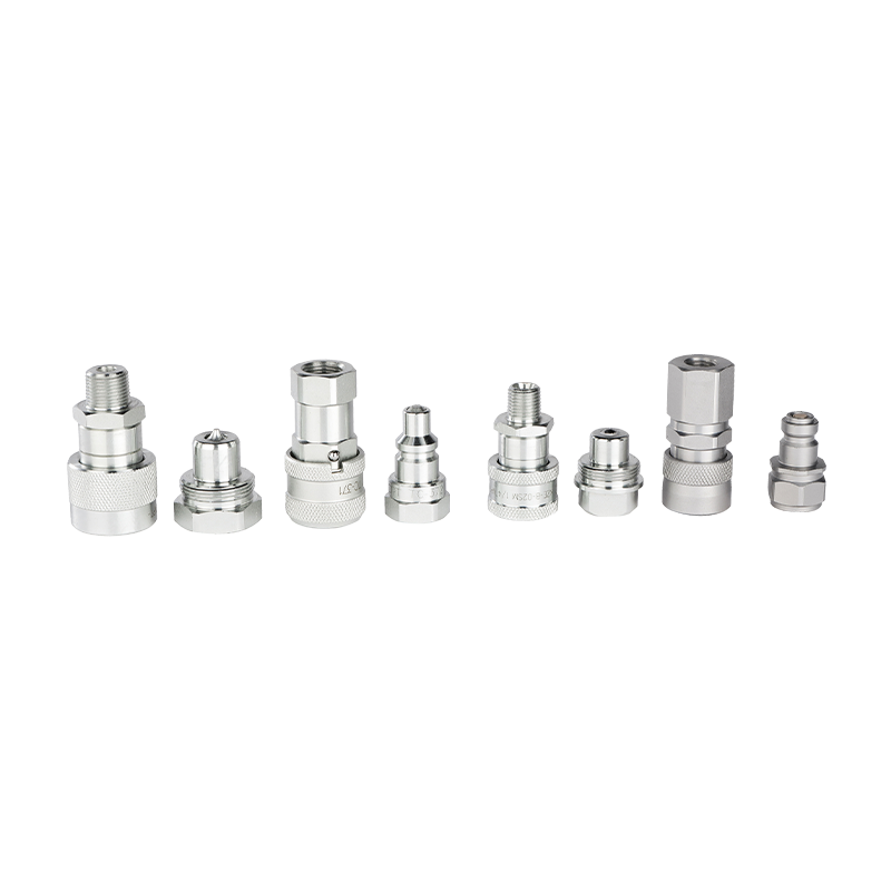 High-Pressure Hydraulic Quick-Connect Couplings for Tool SystemsEnable tool-free connection and disconnection with self-sealing valves, audible engagement, and pressure-tested bodies for hydraulic torque, tensioner, and pump circuits.View Product →
For plants that also run hydraulic torque tools, dryers, and high-pressure circuits side by side, sourcing pressure gauges, couplings and hoses from one supplier keeps thread standards consistent. Companies active in wind, petrochemical and heavy fabrication work can review typical circuit requirements under industry applications before finalising a specification.
Some processes cannot accept the dew point swing of an off-the-shelf unit. Transformer manufacturing is a clear example: the drying system must hold the body under constant positive pressure for days while oil filling proceeds, and any interruption shows up as moisture in the insulation. In those cases the answer is usually a purpose-built assembly, with the desiccant towers, blower, control logic and dew point instrumentation designed as one package rather than assembled from mismatched parts.
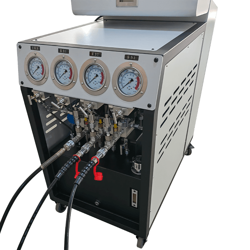 Constant-Pressure Transformer Body Drying SystemMaintains controlled positive pressure with closed-loop sensors, programmable drying parameters, and data logging for transformer core and winding moisture removal.View Product →
Custom-engineered drying packages of this type reuse the same component logic described above: a properly sized separator, a reliable drain, a filtering stage and honest instrumentation. The difference lies in integration and in the acceptance test, which should record dew point at the outlet under load, not only at the factory bench.
Air dryer components are worth specifying individually because they fail individually. Match the separator and drain to real peak flow, hold suppliers to pressure drop, approach temperature and ISO 8573-1 dew point values, and stock the consumables that wear first. That approach keeps moisture out of the line without replacing a healthy dryer every time a dew point reading moves.
If you are specifying components for a combined compressed air and hydraulic maintenance programme, talk to the engineering team about pressure ratings, thread standards and service access before the purchase order is raised.
Quick Contact
Products
Stay In Touch
If you have any questions or need help, feel free to contact with our team.
 Custom Hydraulic Tools and Machinery Manufacturers