English
 English
 عربى
Industry News
Home / News / Industry News / Air in Hydraulic Fluid: Common Causes, Symptoms, and Safe Removal Methods

Content
A torque wrench pump that rattles like it is full of gravel, a gauge needle that jumps instead of holding steady, or a tensioner that creeps after the pressure is set—these are familiar signs of air in hydraulic fluid. The fluid itself is often not the source. In most recurrent cases, free air is entering through the suction side, a low reservoir, or a connection disturbed during service. Bleeding can restore smooth operation, but if the entry point remains open, the air will return as soon as the tool is loaded.
Mineral hydraulic oil can hold roughly 8% to 10% of dissolved air by volume at normal atmospheric conditions. That air is invisible and does not automatically create bubbles or foam. Problems begin when air is entrained—that is, present as free bubbles—or when dissolved air comes out of solution because of a pressure drop on the inlet side of a pump, a sharp return line, or a badly designed reservoir.
Free air changes the fluid’s bulk modulus. In plain terms, the oil becomes spongy. Pressure does not build cleanly, actuators respond late, and the pump has to work harder to move the same load. Under high pressure, bubbles collapse violently near metal surfaces, producing the noise and erosion known as cavitation.
| Condition | Dissolved Air | Free or Entrained Air |
|---|---|---|
| Fluid appearance | Usually clear to slightly hazy; no lasting foam | Milky, foamy, or bubbly, especially at the reservoir |
| Pump sound | Steady and smooth | Whining, knocking, rattling, or gravel-like noise |
| Gauge behavior | Stable under load | Flickering, slow build, or pressure drop after the pump stops |
| Actuator response | Firm and consistent | Spongy, delayed, uneven, or creeping |
| Main risk | Low under normal conditions | Cavitation, heat, seal wear, and inaccurate load control |
Air usually enters on the suction side, because that part of the circuit runs below atmospheric pressure. A loose clamp, a cracked hose liner, a worn O-ring, or a filter housing that is not seated can pull air into the oil without leaving a visible puddle. This is why a system can look dry and still have a persistent air problem.
Quick couplers deserve a closer look because they are opened and reconnected so often. A worn O-ring or a coupler that is only partly seated can admit air on the intake side and weep only under pressure, which makes the leak easy to miss.
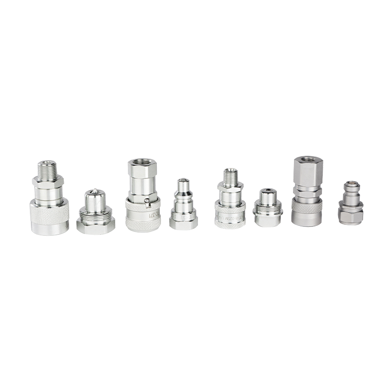 Hydraulic Quick-Connect Couplings for High-Pressure Tool CircuitsSelf-sealing, pressure-tested fittings support clean tool changes and help isolate intake leaks when couplers are checked.View Product →
Start with the simple checks: fluid level, suction clamps, filter seals, and coupler condition. If the oil is milky or foamy, stop running the pump long enough for the foam to settle, then inspect the inlet before adding more fluid.
The first signs are often audible. A pump that whines, knocks, or sounds like it is moving gravel is usually cavitating or struggling with an air pocket. The gauge may flicker, climb slowly, or drop when the pump stops. Actuators feel spongy, and a cylinder may creep after the valve is closed.
In bolting work, the effect is not just cosmetic. A hydraulic tensioner with air in the circuit can extend unevenly, so the indicated pressure does not translate into a consistent bolt load. A torque wrench may stall, overrun, or deliver scatter across a flange. A jack can lift unevenly and then settle. Over time, cavitation erodes pump parts and valve seats, while the extra heat degrades seals and shortens fluid life.
A stable pressure reading is one of the simplest diagnostic tools. A gauge that holds steady under load points away from free air; a needle that pulses or falls back suggests aeration, a restricted inlet, or a leaking suction line.
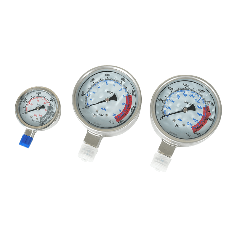 Hydraulic Pressure Gauges for Pump and Tool DiagnosticsGlycerin-damped, overload-protected gauges provide steady pressure readings for monitoring pumps, torque wrenches, tensioners, and jacks.View Product →
If the gauge is steady but the actuator still behaves poorly, check the tool itself. Trapped air in a tensioner or wrench body can produce the same spongy feel even when the pump is healthy.
Bleeding is straightforward, but the sequence matters. The goal is to remove free air without driving more into the system or creating a safety hazard.
Do not confuse a quiet pump with a clean circuit. After bleeding, load the tool and watch the gauge and actuator response. If air returns within a short period, stop repeating the bleed procedure and look for the entry point.
Hydraulic bolt tensioners are particularly sensitive to air because the stroke is short and the load is high. Air in the tensioner or hose can make the piston advance slowly, produce a soft pressure build, and leave bolts with uneven preload. Bleed at the tensioner’s highest port, cycle the piston without load first, and then verify under a controlled load.
Torque wrenches can show air as erratic ratcheting, a stalled motor, or torque scatter. Check the pump inlet, the hose couplers, and the wrench connection before adjusting the pressure setting. A wrench that behaves well at low torque but falters under load is often drawing air at the pump inlet rather than at the tool.
Jacks should be bled with the load removed. Air in a jack can cause a spongy lift, slow extension, or creep after the valve is closed. Cycle the jack through its full stroke, bleed at the highest point, and check that the hose does not loop upward and trap air.
For pump setup and tool matching, the bolt tensioning pump guide covers precision types and field best practices.
Most persistent air problems are not solved by adding more fluid or bleeding longer. They are solved by finding the point where air enters and correcting it.
If the system stays smooth after one or two bleed cycles, the air was probably introduced during service. If it returns under load, treat the pump inlet and suction side as the first suspects. A properly sealed circuit will hold its fluid level and pressure behavior over repeated cycles. When a tool or pump continues to perform inconsistently, contact our team with the circuit details, fluid condition, and gauge readings so the issue can be checked against the tool’s operating requirements.
The variety of models, to meet the development needs of various regions in the world.
Quick Contact
Products
Stay In Touch
If you have any questions or need help, feel free to contact with our team.
 Custom Hydraulic Tools and Machinery Manufacturers